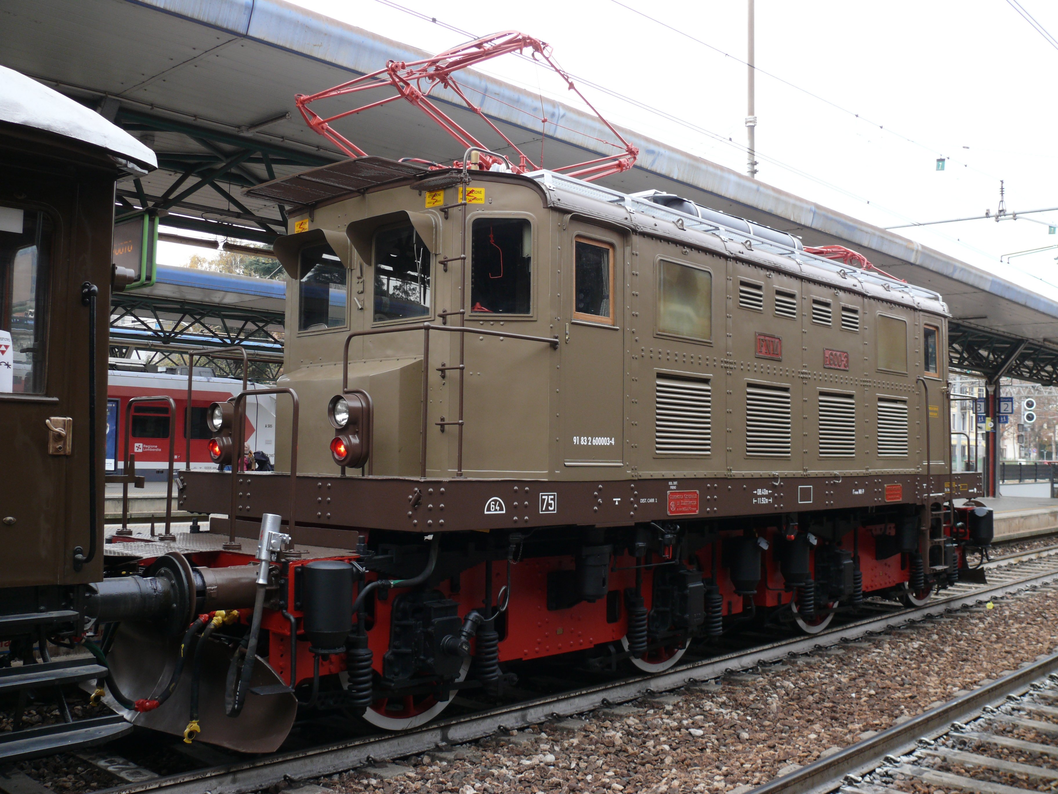
Jointly designed with the Officine Meccaniche in Milan and the Compagnia Generale di Elettricità at the end of the 1920s, the 6 class E 600 locomotives were the first 3000 V. CC electric vehicles. They were introduced by FNM to launch the electric traction service on the Milano-Saronno and Milano-Meda lines, opened in 1929. They consist of a riveted and bolted metal body which rests with its frame on two bogies via the use of sprung struts. The bogies consist of riveted steel plates bolted together to form a robust frame. They house the 4 traction motors and are joined together with a ball joint. The buffing and draw gear components and the pneumatic and electrical heating connections for the train are located at the head sections. From the driving cab, the train crew can move between the locomotive and the train via a front door and a gangway present on the bogie platform. Two pantographs for collecting power from the overhead lines are located on the roof.
E-600

- Progettazione: 1927
- Costruzione: 1928-29
- Esercizio: 1928-presente
- Massa in servizio: t.64
- Rodiggio: Bo’ Bo’
- Ruote motrici Ø: 1.250 mm
- Costruttore: OM-CGE Milano
- Lunghezza fuori tutto: 11.920 mm
- Larghezza: 2.850 mm
- Rapporto di trasmissione: 24/86
- Potenza oraria Motori CT 350: 1.030 kW
- Forza trazione oraria: 88,3 kN
- Altezza imperiale: 3.800 mm
- Interperno carrelli: 5.600 mm
- Passo carrelli: 2.800 mm
- Sforzo all’avviamento: 147 kN
- Velocita massima: 75 Km/h
- Alimentazione: 3 kV CC
- Design date: 1927
- Build date: 1928-29
- Service date: 1928-presente
- Service mass: 64 tons
- Wheel arrangement: Bo-Bo
- Diameter of the driving wheels: 1,250 mm
- Builder: OM-CGE Milan
- Overall length: 11,920 mm
- Width: 2,850 mm
- Gear ratio: 24/86
- 1-hour power CT350 motors: 1,030 kW
- 1-hour tractive effort: 88.3 kN
- Roof height: 3,800 mm
- Distance between bogie centres: 5,600 mm
- Bogie wheelbase: 2,800 mm
- Starting tractive effort: 147 kN
- Maximum speed: 75 Km/h
- Voltage: 3 kV CC
Inside, the body is divided into three sections. The two driving cabs at each end are equipped with large front and side windows. They house the control panels for the various services, the handle-operated controller for forward/reverse movement and speed, the brake cocks, the light switches, the whistle and the handbrake wheel. The two cabs are connected via a corridor accessed from doors positioned behind the driver which also separate the compartment for high-voltage equipment. The corridor runs through the central part of the body, where the electrical equipment is housed, protected by grating walls: specifically the contactors, rheostats and compressors. The cabs originally had access doors on both sides. The left-hand door of each cab was later removed. During modernisation work carried out in the 1980s, the body of the E 600.3, its colour and other cosmetic details were kept as close as possible to its appearance in the ‘50s - ‘70s as a historic locomotive.

