
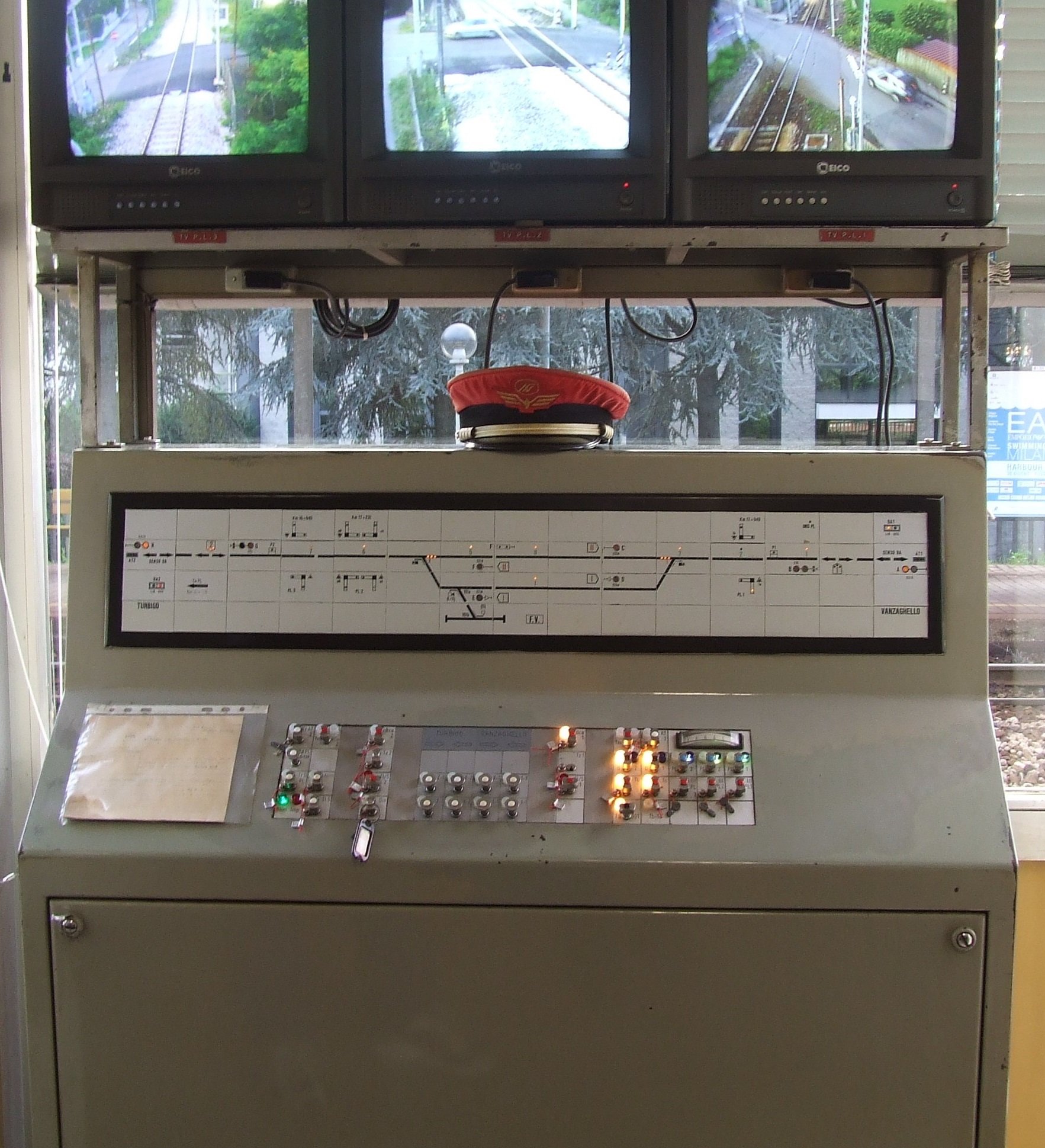
ACEI and DCO control panels
Interlocking levers refers to the set of systems and devices for controlling and operating the equipment of a station (points, signals, ground signals, level crossings etc.), controlled from a single command post. Interlocking levers serves to establish control and connection between all of this equipment, thus ensuring the transit or manoeuvring of a consist in complete safety. The Italian ACEI (electric interlocking levers) in particular is the finest example of the development of rail traffic management in the second half of the 20th century, and paved the way for modern computerised central interlocking, in conjunction with the use of electronics, of the ACC and ACC – M types.
The schematic plan of a station is a drawing (once created by hand) which shows a diagram of all the station equipment: tracks, switches (plus related equipment for shunting and control), buildings, signals, track circuits, markers for the origin points of routes, any level crossings (plus related equipment for shunting and control), etc.
Gallery
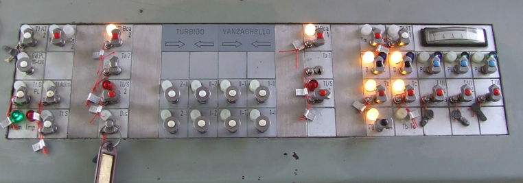
View of the ACEI movement control panel at Castano Primo. From left to right we can see the emergency buttons and levers, route buttons, levers for individual control of the points and level crossings and an ammeter to measure power consumption when operating them. 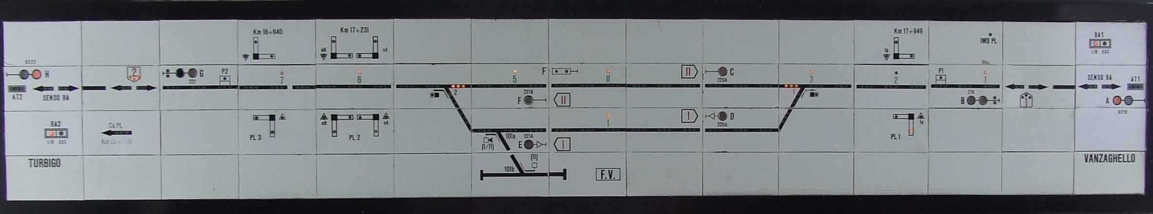
ACEI light-up display at Castano Primo. View of the ACEI light-up display (of the tile type). The display represents a diagram of the station yard with all the equipment (tracks, signals, level crossings, block instruments). Optical and acoustic signals from the equipment make it possible to check that everything is functioning correctly and to track the movement of a consist within the station. 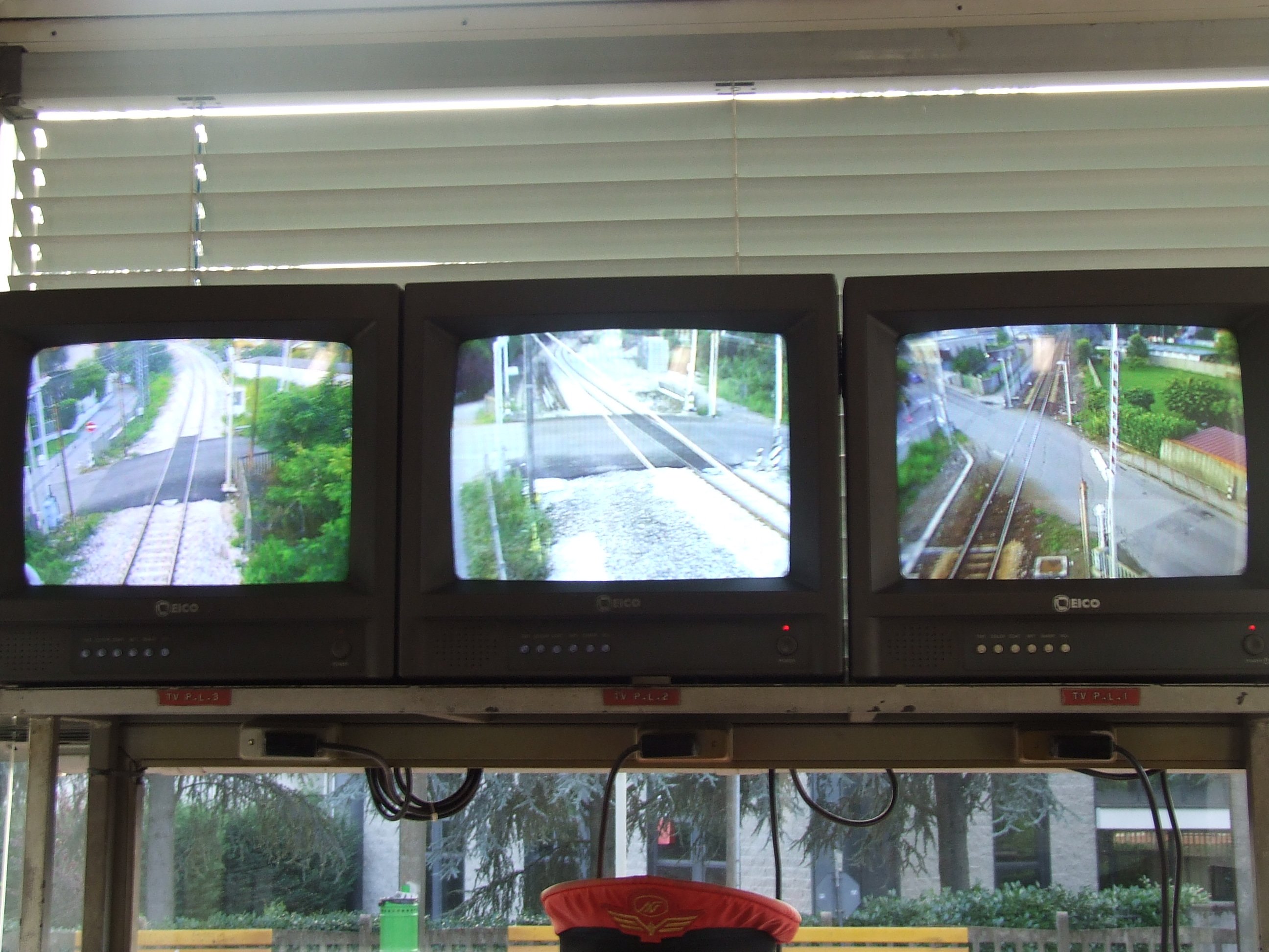
TV system of the ACEI at Castano Primo for checking the level crossings. These monitors allowed staff in charge of movement to make a further visual check that the level crossings at the station had been correctly closed. 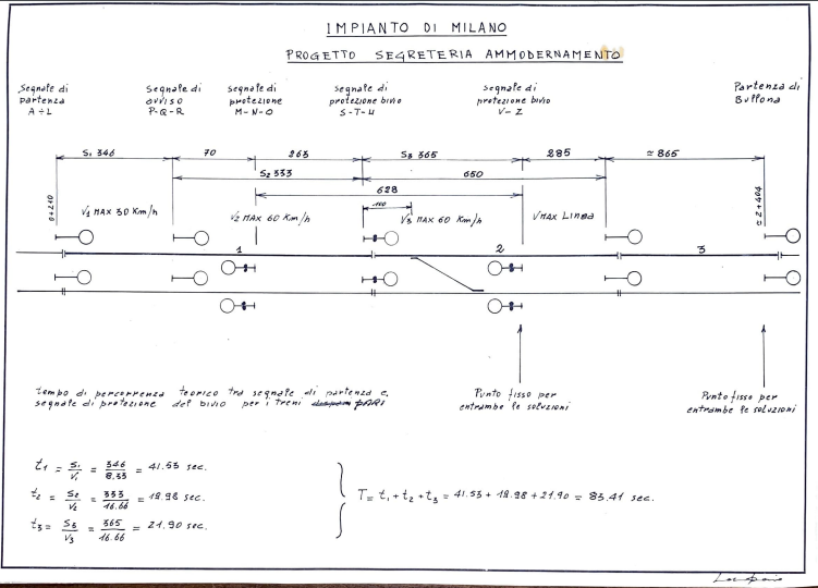
This transparency shows the plan to modernise the Milano Cadorna system, describing distances, maximum speeds allowed and theoretical journey times of the trains following conversion of the line to two-way (even and odd trains could circulate on both tracks). 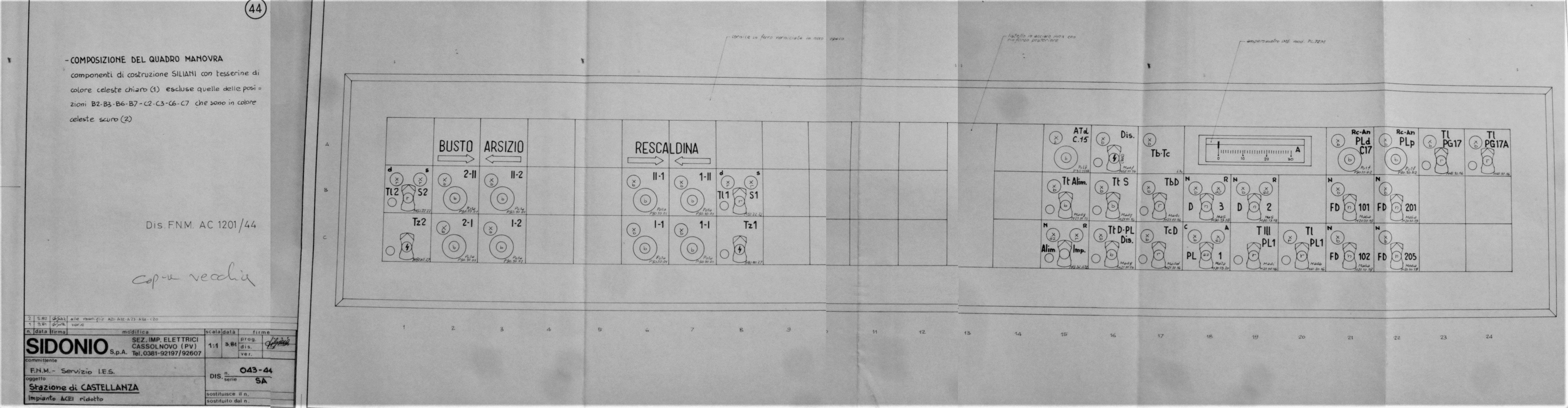
Castellanza ACEI Control Panel schematic plan - March 1981 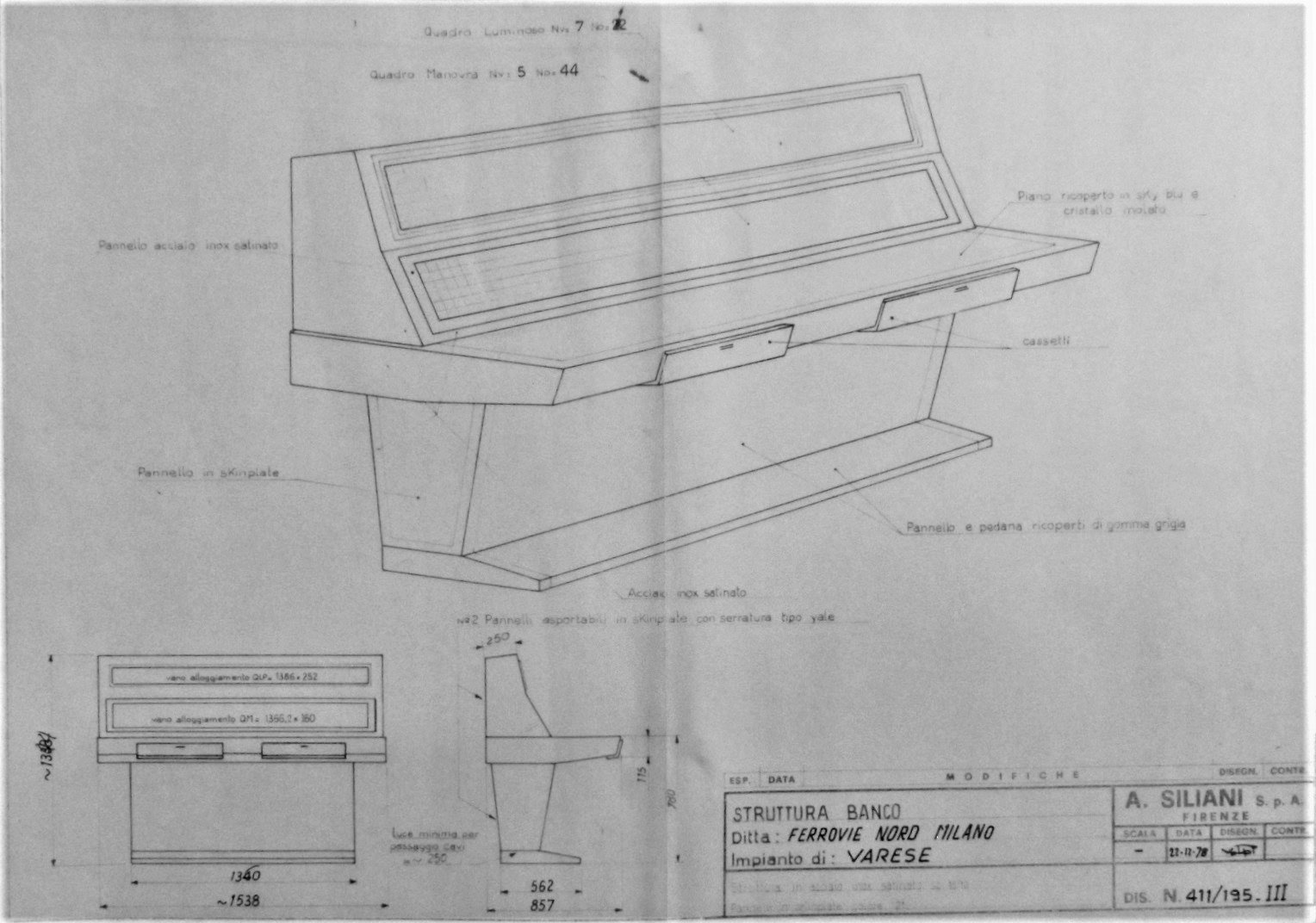
Varese Nord ACEI control panel - Desk Structure - 22 December 1978 
ACEI at Merone station - Schematic Plan and Control Panel - June 1982 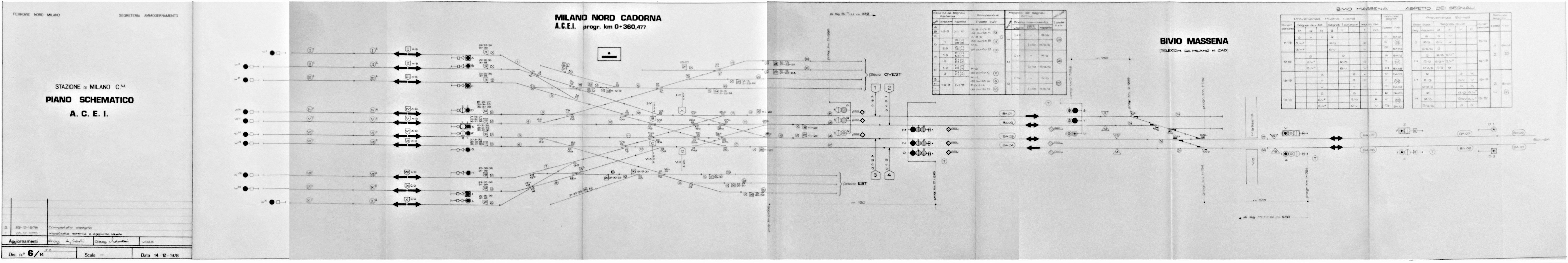
Schematic Plan of the ACEI at Milano Cadorna and Bivio Massena - 14 December 1978